Introduction digital communication system:
Our goal is to acquire a basic understanding of digital communications. To do so, we study the basic design and analysis principles of digital communication systems. This set of notes is written for the purpose. It can be divided into two parts. The first part describes, in detail, some common digital modulation and demodulation techniques, which form the basis of digital communications. The second part presents a survey of various advanced topics, such as synchronization, equalization, diversity reception, and error control coding. The combination of the two parts aims to provide a solid introduction to modem digital communication theory.
Overview of Digital communication system
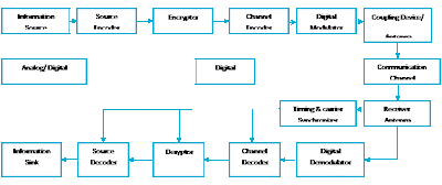
A digital communication system conveys information in digital form from a source to one or more destinations through a communication channel. Figure 0.1 gives the block diagram of a typical digital communication system. The “standard” components shown in Figure 0.1 include (in the order of the flow of information):
1. Information source or input transducer
2. Source encoder
3. Encryptor
4. Channel encoder
5. Digital modulator
6. Communication channel
7. Timing and carrier synchronizer
8. Digital demodulator
9. Channel decoder
10. Decryptor
11. Source decoder
12. Information sinks or output transducer
 |
| Figure 0.1 |
The first five components, which are pertinent to the transmission of information, form the transmitter of the communication system. The last six components, which are pertinent to the reception of information, make up the receiver of the communication system. We point out that some of the components above may not be found in some digital communication systems. However, any digital communication system should contain a modulator, a demodulator, and a synchronizer. Our main focus is on these three components. Later in the notes, we will briefly introduce the concept of channel coding (error control coding). Source coding and encryption are not covered here.
To facilitate the design and evaluation of communication systems, we need to establish a measure of performance. For a digital communication system, a common performance measure is the probability of the event that an error 1 occurs at the receiver. There are many such error events, at various stages of the reception; we can employ to set up our performance measure. In most of the discussions followed, we use the average symbol error probability (or the average bit error probability in the cases of binary symbols) at the output of the demodulator as our performance measure. This is the probability that the symbol estimate given by the demodulator does not correspond to the transmitted symbol. In a (channel) coded system, we also use the average symbol error probability at the output of the (channel) decoder as a measure of performance. We again would like to point out that the average symbol error probability may not be the most meaningful performance indicator in some systems. For example, the quality of the received speech may be a more meaningful performance measure in a voice communication system. Nevertheless, due to its simplicity and generality, we (and most communication researchers) adopt the average symbol error probability as the performance measure based on which we evaluate and design digital communication systems. With this in mind, we study some common analysis techniques to obtain the average symbol error probabilities of different communication systems. Our primary design objective is to minimize the average symbol error probability of a digital communication system.
No comments:
Post a Comment