Friday, July 5, 2013

History of digital communication system

First Generation Cellular Systems

The first generation cellular systems generally employ analog Frequency Modulation (FM) techniques. The Advanced Mobile Phone System (AMPS) is the most notable of the first generation systems. AMPS were developed by the Bell Telephone System. It uses FM technology for voice transmission and digital signaling for control information. 

Other first generation systems include:
• Narrowband AMPS (NAMPS)
• Total Access Cellular System (TACS)
• Nordic Mobile Telephone System (NMT-900)

All the first generation cellular systems employ Frequency Division Multiple Access (FDMA) with each channel assigned to a unique frequency band within a cluster of cells.

Second Generation Cellular Systems

The rapid growth in the number of subscribers and the proliferation of many incompatible first generation systems were the main reason behind the evolution towards second generation cellular systems. Second generation systems take the advantage of compression and coding techniques associated with digital technology. All the second generation systems employ digital modulation schemes. Multiple access techniques like Time Division Multiple Access (TDMA) and Code Division Multiple Access (CDMA) are used along with FDMA in the second generation systems. 

Second generation cellular systems include: 
• United States Digital Cellular (USDC) standards IS-54 and IS-136
• Global System for Mobile communications (GSM)
• Pacific Digital Cellular (PDC)
•CDMA One

Third Generation Cellular Systems

In October 2001, Japan was the first country in the world to introduce 3G services to a 30km radius around Tokyo. Europe and the US are releasing GPRS systems and testing 3G technologies and strangely enough the Isle of Man is set to be the next 3G contender.
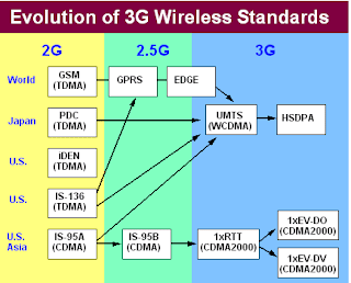
Evaluation of 3G
Figure-1.3

 Why 3g

Third generation cellular systems are being designed to support wideband services like high speed Internet access, video and high quality image transmission with the same quality as the fixed networks. The primary requirements of the next generation cellular systems are:

• Voice quality comparable to Public Switched Telephone Network (PSTN).
• Support of high data rate. The following table shows the data rate requirement of the 3G systems.
• Support of both packet-switched and circuit-switched data services.
• More efficient usage of the available radio spectrum
• Support of a wide variety of mobile equipment
• Backward Compatibility with pre-existing networks and flexible introduction of new services and technology.
• An adaptive radio interface suited to the highly asymmetric nature.
• Internet communications: a much greater bandwidth for the downlink than the uplink.

Today's 2G GSM mobile phones can download 9.6kbper second. 3G technologies promise up to 2 Mbps. The technology has been on the cards for some time now but the introduction of these services has been beset by problems.

Digital Communication Channels

The communication channel provides a connection through which the information-bearing signal prop-agates. It is perhaps the most important component of a communication system. The design of all other components in Figure 0.1 depends heavily on the characteristics of the communication channel. There are many different types of physical communication channels, such as: 
1. Wire line channels 
2. Wireless channels 
3. Fiber optic channels 
4. Underwater acoustic channels 
5. Storage channels 

Different kinds of channels can have very different characteristics. In order to design an “efficient” digital communication system over a specific communication channel, we need to study the characteristics of the channel extensively and carefully. Unfortunately, this is impractical for our general treatment on digital communication theory. Instead, we adopt a model-based approach here, i.e., we construct a generic mathematical channel model to represent a "typical" communication channel. For this purpose, our channel model describes the physical communication channel as well as the properties of the equipments, such as antennas and amplifiers, necessary to access the channel. The model not only needs to be general enough to approximate most of the physical channels described above, but also simple enough to facilitate the analysis and design of the communication system. To this end, we notice that the major characteristic of a communication channel we are interested in is how the channel distorts the information-bearing signal. 

We start by listing out some common channel defects: 
1. Thermal noise in the electronic devices 
2. Signal attenuation 
3. Amplitude and phase distortion 
4. Multi path distortion 
5. Finite-bandwidth (low pass-filter) distortion 
6. Impulsive noise 

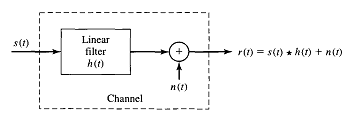
Based on knowledge of these channel defects, we construct the generic channel model. Suppose we use the symbol s(t) to denote the transmitted signal at the output of the modulator, then it is found that the following linear filter model (see Figure 1.2) sufficiently approximates the behaviors of many typical communication channels:

Where r(t) represents the received signal at the input of the demodulator, n(t) is a random process which models the thermal and impulsive noises, and c(z; t) is a linear time- varying filter 2 which models the other channel distortions listed above. We note that the linear (time-varying) channel model in (1) is very general and we work with simplifications of this model in many cases. Among the various common simplifications of the general model, the additive white Gaussian noise (AWGN) model is perhaps the most studied and important. In the AWGN model, c(;t) =δ() and (1) reduces to 

r(t)=s(t)+n(t); (2)

Where n(t) is a zero-mean wide-sense stationary Gaussian random process with auto-correlation function. 

Rn()=(Nο/2) *δ(
Linear filter channel model
 Figure 1.2

The factor No/2 is called the two-sided noise spectral density of the noise n(t). This model is primarily employed to represent the situation in which the only channel defect is the thermal noise in the electronic devices of a communication system. Although AWGN channels are rare in practice (except in deep space communications), because of its simplicity, we use the AWGN model as the cornerstone of our introduction to digital communications. 

DIGITAL COMMUNICATION SYSTEM

Introduction digital communication system:

Our goal is to acquire a basic understanding of digital communications. To do so, we study the basic design and analysis principles of digital communication systems. This set of notes is written for the purpose. It can be divided into two parts. The first part describes, in detail, some common digital modulation and demodulation techniques, which form the basis of digital communications. The second part presents a survey of various advanced topics, such as synchronization, equalization, diversity reception, and error control coding. The combination of the two parts aims to provide a solid introduction to modem digital communication theory.

Overview of Digital communication system

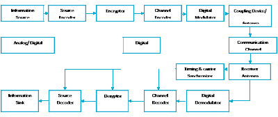
A digital communication system conveys information in digital form from a source to one or more destinations through a communication channel. Figure 0.1 gives the block diagram of a typical digital communication system. The “standard” components shown in Figure 0.1 include (in the order of the flow of information):

1. Information source or input transducer 
2. Source encoder 
3. Encryptor 
4. Channel encoder 
5. Digital modulator 
6. Communication channel 
7. Timing and carrier synchronizer 
8. Digital demodulator 
9. Channel decoder 
10. Decryptor 
11. Source decoder 
12. Information sinks or output transducer

Block diagram of a typical Digital Communication System
Figure 0.1
The first five components, which are pertinent to the transmission of information, form the transmitter of the communication system. The last six components, which are pertinent to the reception of information, make up the receiver of the communication system. We point out that some of the components above may not be found in some digital communication systems. However, any digital communication system should contain a modulator, a demodulator, and a synchronizer. Our main focus is on these three components. Later in the notes, we will briefly introduce the concept of channel coding (error control coding). Source coding and encryption are not covered here.

To facilitate the design and evaluation of communication systems, we need to establish a measure of performance. For a digital communication system, a common performance measure is the probability of the event that an error 1 occurs at the receiver. There are many such error events, at various stages of the reception; we can employ to set up our performance measure. In most of the discussions followed, we use the average symbol error probability (or the average bit error probability in the cases of binary symbols) at the output of the demodulator as our performance measure. This is the probability that the symbol estimate given by the demodulator does not correspond to the transmitted symbol. In a (channel) coded system, we also use the average symbol error probability at the output of the (channel) decoder as a measure of performance. We again would like to point out that the average symbol error probability may not be the most meaningful performance indicator in some systems. For example, the quality of the received speech may be a more meaningful performance measure in a voice communication system. Nevertheless, due to its simplicity and generality, we (and most communication researchers) adopt the average symbol error probability as the performance measure based on which we evaluate and design digital communication systems. With this in mind, we study some common analysis techniques to obtain the average symbol error probabilities of different communication systems. Our primary design objective is to minimize the average symbol error probability of a digital communication system.